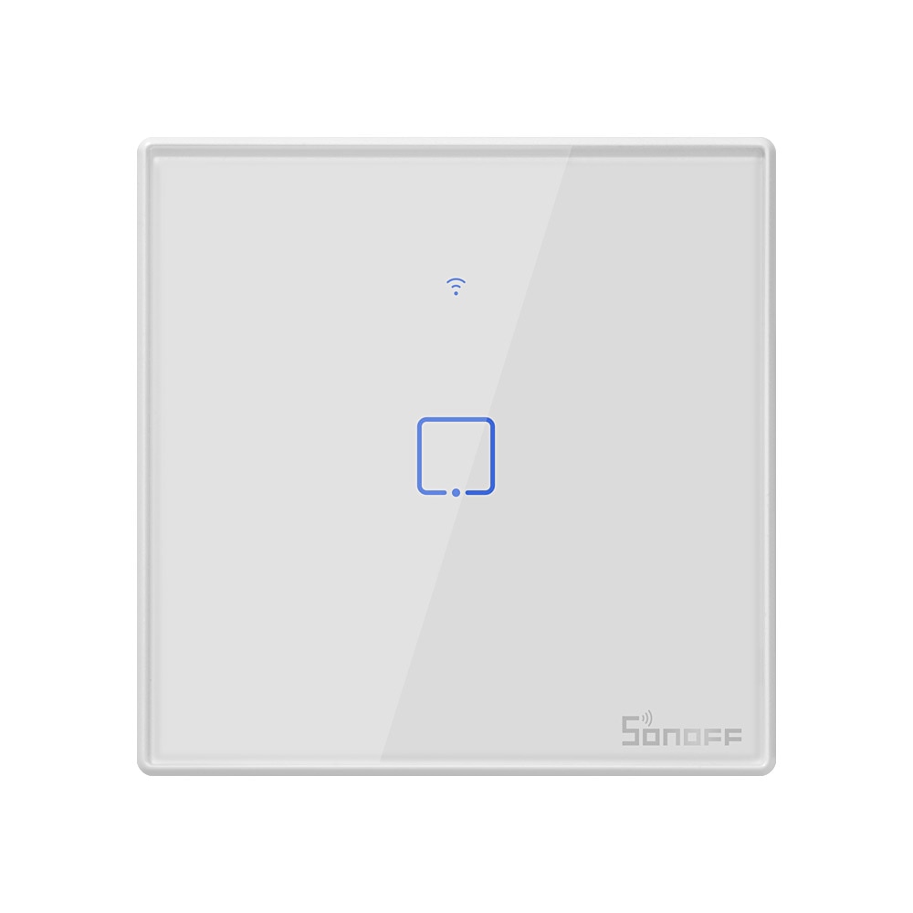

#SONOFF TOUCH SCREEN SERIAL#
The screen then has serial commands mapped to UI elements and can be sent and received from ESPHome firmware to control it. are created using Nextion Editor software, and then then the project files/assets are uploaded directly into the Nextion screen. It also contains a temperature + humidity sensor and two integrated low-amp relays for 220V/300W or 110V/150W capacity respectively, but the point is really for it to act as remote control of scenes and running widgets (local applications or scripts) such as for example an HVAC thermostat.Īs I understand all Nextion displays as their own integrated microcontroller unit (STM32GO ARM Cortex-M0+ 64MHz Onboard MCU Processor) so that will off-load most of the heavy lifting work and all text and graphics, animations, etc. Looks like a model each for Europe and North America “NSPanel-EU” and “NSPanel-US”. Many tech review bloggers/vloggers who received preview prototype units seem to complain about its lack of integrated motion sensor for presence detection so can automatically turn on the screen backlighting, (and I like to also add the request for its DS18B20 temperature-only sensor to be replaced with a DHT22, AM2301, or Si7021 temperature and humidity combo sensor). It is listed at MSRP $74.90 but early-bird version is currently sold via this Kickstarter campaign for around $54 each or $99 for two:Ī lot of information had already leaked via its FCC certification (FCC ID 2APN5NSPANEL): Request support in ESPHome for SONOFF NSPanel touchscreen display by ITead = ESP32 based with custom Nextion HMI screen: The Switch LED is on all the time, even when the switch is off so you can easily find the switch in the dark.Īlternatively, you can solder the switch LED on 3.3v and ground but then you can't control the LED, it is always on and very bright.Describe the problem you have/What new integration you would like Solder the switch LED where the Wi-Fi LED is and then you can control the LED by using the command LedPower ON. Control ON/OFF Leds on Sonoff Touch solution ~

The PSF-A85 in the Sonoff Touch does not have the external antenna connector soldered on. That is where the external antenna connector is located in the images above. Pay attention to the corner of the chip with three unused solder contacts. Note: Even if you have the PSF-A85 chip inside instead of a default ESP8285, the GPIO0 pin is in the same location. GPIO0 can be found on the right side of the ESP8285 and is the second pin from the bottom, as can be seen on the pictures. A connection between GPIO0 and GND needs to be made manually. The Sonoff Touch button is not connected to GPIO0 and hence cannot be used to bring the module into Programming Mode. Be sure to not touch it directly during the modifications. The touch sensor should be back in its intended place.

The four serial pins (3V3, Rx, Tx, GND) can be seen in the pictures for the US version (left) and the EU version (right) of the module PCB.īe careful while removing and reassembling the top PCB. The hidden underside of the PCB contains the ESP8285 as shown in the pictures. Carefully remove the top PCB from the assembly. Please see the Hardware Preparation page for general instructions.Īs always, you need to access the serial interface. Unlike most Sonoff modules, the Sonoff Touch is based on the ESP8285 rather than the ESP8266. Smart Home Integrations Smart Home Integrations.


 0 kommentar(er)
